General Guidelines
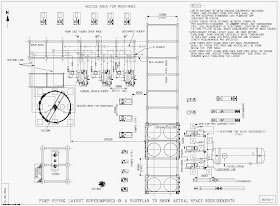
Following sketch (sketch-1) shows a portion of a typical plot plan with few Equipment's, pipe rack etc shown. For equipment spacing pl refer, plant layout and piping specification number P-GS-PL-003, GE Gap guidelines, and/or OISD 118.
 |
| Pump Piping Layout superimposed in a plot plan |
- Pump location will affect the piping routing and supporting. Pumps carrying hydrocarbons and materials above 230 degree C shall not be located below pipe racks, structures, air fin coolers and vessels. Those in non-flammable service may be located beneath the pipe rack without obstructing the access bay, other maintenance requirements of the respective process unit.
- Pumps shall be located as close to the source of suction in order to minimize pressure drop in the system. The line size and temperature will be the determining factors in piping layout.
- A preliminary piping layout ( study layout ) shall be made to determine the requirement of spacing between pumps especially in case of side suction/ side discharge, top suction/ top discharge pumps where straight length requirement / platform / CPS requirement etc have to be considered.
- Reducers in pump suction lines shall be as close as possible to the pump suction/discharge nozzles.
- Eccentric reducers in pump suction lines shall be flat on top in order to prevent any entrained vapours in the liquid from accumulating in the high point ( if installed bottom flat ) and thus causing cavitation in the pump. Pumps in boiler feed water service operating close to vapour pressure of the liquid are susceptible to this type of problems.
- Reducers in pump discharge should be concentric in most cases. Eccentric reducers may be used in both suction and discharge piping for top suction/top discharge pumps in order to obtain clearance between suction and discharge piping.
- Consideration must be given to lube oil and seal oil systems and any cooling water requirements. Care must be exercised not to block access to the pump seals and bearings when routing these lines.. The pump data sheet should always be reviewed to make sure these requirements are not missed. For very large pumps these may be separate on skids.
- When developing an equipment layout in pump areas, the layout designer must envision potential obstructions around the pumps (e.g. large block valves, steam turbine piping, and tee-type pipe supports from grade). As per Oil Industry Safety Directorate stipulation ( OISD 118 ) 1 mtr (1000mm ) is the minimum accepted spacing between pumps.
- Auxiliary piping shall be neatly routed along the base-plate and shall not extend across the operating floor. This piping shall not obstruct inspection covers, bearing caps, upper halves of casings or any other items which require access for operation or maintenance. In order to avoid a fire hazard, lubricating oil, control oil and seal oil pipes shall not be routed in the vicinity of hot process or hot utility pipes.
 |
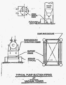
| Typical pump suction piping at vacuum tower |
- Cooling water pipes to pumps and compressors shall not be less than 20NB. Pipes 25NB or less shall have the take-off connection from the top of the header in order to prevent plugging during operation.
- When flexibility loops are required between pumps, it is necessary to partially run the lines over the pump and driver. Every effort must be made to minimize maintenance obstructions by running the piping either outside the area directly over the pumps or at a high enough elevation to permit the removal of the pump or driver.
- The pump shall be placed in such a manner so that the suction nozzle elevation is always below the vessel/tank nozzle and suction pipe shall be routed so that there is no pockets.
- Pumps in vacuum service present special problems. Since the system operates at a negative pressure and very high temperature, the pumps must be located very close to the suction source. This is often directly below the tower or immediately outside the tower support columns. Pumps located directly beneath the tower can be mounted on a special spring base as shown in sketch below.
- In some rare cases one pump is installed as a common spare between two other pumps in different services. The pump must be manifolded in such a way to accomplish this.
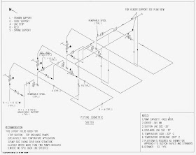
- Pumps may be single-stage or multi-stage. Multi stage pumps are usually side suction side discharge. These pumps require significantly more space and faces layout problems. There is usually a straight run requirement (example, 5 pipe diameters) between the suction flange and the first elbow as shown in Sketch. Due to the heavier casing design for high pressures, allowable nozzle loads are often higher for multi-stage pumps making pipe stress problems somewhat easier to resolve.
 |
| Piping Isometric Sketch |
- The location of valves, strainers, spacers/blinds etc. needs special consideration. The option of placing the valves at a higher elevation and providing an operating platform has got its own advantages and disadvantages. If valves are provided at a higher elevation the accessibility for the pumps is enhanced but the operability of the valves becomes difficult.
- It shall be noted that even if the type of pump is same, different piping layouts may be followed. So it is not always necessary that same layout shall be followed for same type of pumps, but is governed by various factors such as temperature, requirement of vertical strainers etc.


Good article to learn basics of the piping layout and pump layout...also discussed little for the maintenance and access requirements.
ReplyDeletewhat is the difference between ASME Sec III Div.1 and ASME Sec III Div.3??
ReplyDelete