Bell-and-Spigot Joint
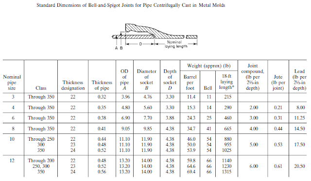
This joint for underground cast-iron pipe was developed as long ago as 1785. Standard dimensions are shown in Table below:
The joint may be made up with lead and oakum, sulfur compounds, or cement. Lead and oakum constitute the prevailing joint sealer for sanitary systems. Belland-spigot joints are usually reserved for sanitary sewer systems. These joints are not used in ductile iron pipe.
Mechanical (Gland-Type) Joint
This modification of the bell-and-spigot joints, as designated in Federal Specification WW-P-421 and ANSI/AWWA C111/A21.11, is illustrated in Table given below:
This joint is commonly used for low and intermediate-pressure gas distribution systems, particularly those conveying natural gas or dry manufactured gas.
 |
| Mechanical (gland-type) joint for cast-iron pipe |
Mechanical joints are also used for water lines, sewage, and process piping. In the mechanical (gland-type) joint shown in Fig. A2.30, the lead and oakum of the conventional bell-and-spigot joint are supplanted by a stuffing box in which a rubber or composition packing ring, with or without a metal or canvas tip or canvas backing, is compressed by a ductile cast-iron follower ring drawn up with bolts. In addition to making an inherently tight joint even under considerable pressure, this arrangement has the advantage of permitting relatively large lateral deflections (31.. to 7 ), as well as longitudinal expansion or contraction. For more details, refer to AWWA C600, Standard for Installation of Ductile-Iron Water Mains and Their Appurtenances.
Tyton Joint
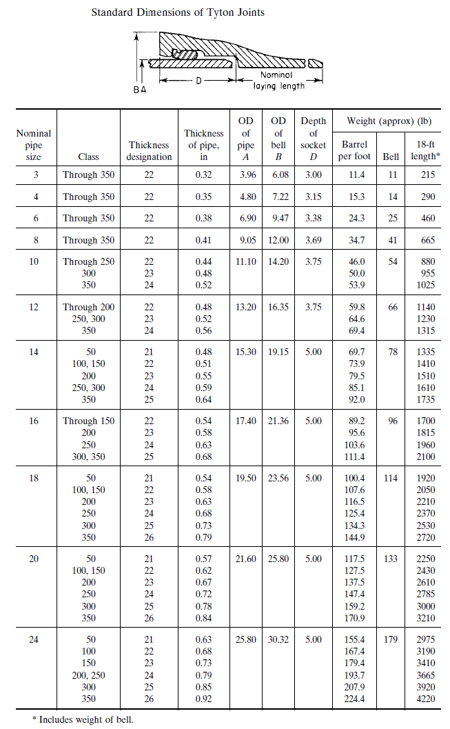
The Tyton joint is designed to contain an elongated grooved gasket. The inside contour of the socket bell provides a seat for the circular rubber in a modified bulb shaped gasket. An internal ridge in the socket fits into the groove of the gasket. A slight taper on the plain end of the pipe facilitates assembly. Standard dimensions are given in Table A2.24. The maximum joint deflection angle is 5 for sizes through NPS 12 (DN 300), 4 for NPS 14 (DN 350) and NPS 16 (DN 400), and 3 for NPS 18 (DN 450), NPS 20 (DN 500), and NPS 24 (DN 600). Either all-bell U.S. standardized mechanical joint fittings or bell-and-spigot all-bell fittings with poured or cement joints can be used with Tyton joint pipe.
Mechanical Lock-Type Joint
For installations where the joints may tend to come apart owing to sag or lateral thrust in the pipeline, a mechanical joint having a self-locking feature is used to resist end pull. This joint is similar to the gland-type mechanical joint except that in the locked joint the spigot end of the pipe is grooved or has a recess to grip the gasket. Although only slight expansion or contraction can be accommodated in this type of joint, it does allow the usual 3¹⁄₂ to 7 angular deflection. The lock-type joint finds application aboveground in the process industries and in river crossings on bridges or trestles, as well as in submarine crossings or in unusually loose or known marshy soils. Where the locking feature is on the spigot rather than on the bell, this type of pipe can be used with the regular line of mechanical joint fittings.
Mechanical Push-On-Type Joint
Where a low-cost mechanical joint is desired, the roll-on type can be used. In this joint, a round rubber gasket is placed over the spigot end and is pulled into the bell by mechanical means, thus pulling the ring into place in the bottom of the bell. Outside the rubber gasket, braided jute is wedged behind a projecting ridge in the bell. This serves to confine the gasket under pressure in the joint. A bituminous compound is used to seal the mouth of the bell and to aid in retaining the hemp and the rubber gasket. Either bell-and-spigot or mechanical (gland-type) fittings are used with this line of pipe. Push-on joints are made in accordance with ANSI/AWWA C111/A21.11.
This article is continued to Part 2, Read here -Joining Ductile Or Cast-Iron Pipe - Part 2
Tagged as :
Piping
Piping Design


0 comments :
Post a Comment